Physical Address
Suite 5, 181 High Street,
Willoughby North NSW 2068
Physical Address
Suite 5, 181 High Street,
Willoughby North NSW 2068
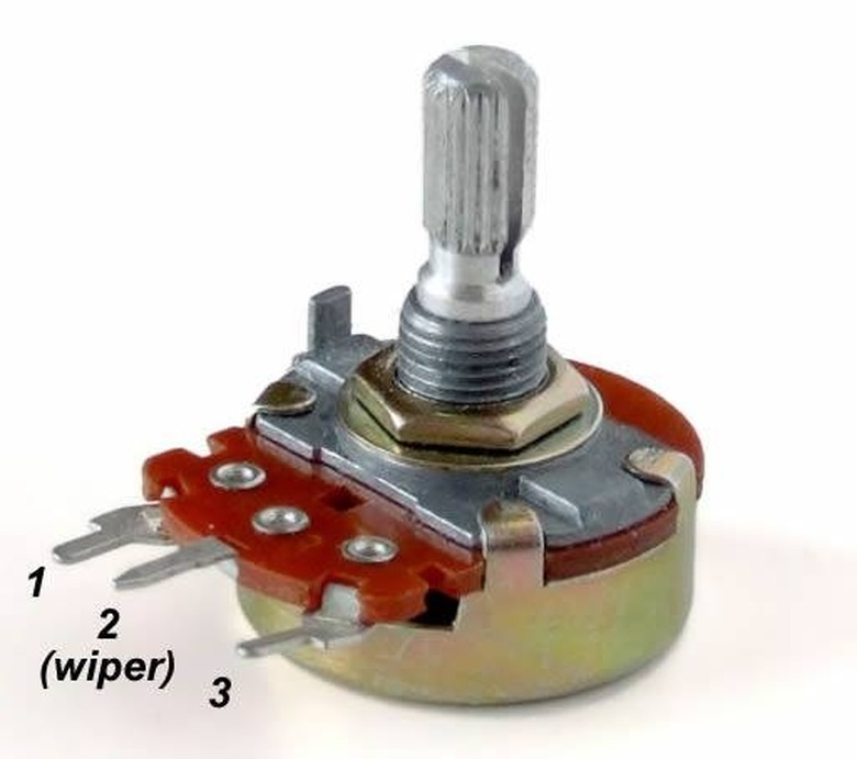
A potentiometer, or “pot” for short, is also known as a variable resistor. Variable resistors are used to dynamically change the resistance to control the current in a circuit, and may also be used as a voltage divider. For example, they are used to control the volume in a radio. Potentiometers differ from regular resistors in that they have three terminals instead of two. The middle terminal is the “wiper.” When a potentiometer is used as a voltage divider, all three terminals are wired separately. But when the potentiometer is wired as a rheostat, only two connections are needed. Either side of the variable resistor may be attached to the circuit board, with the remaining side unattached or grounded, but it is important to always connect the wiper. The wiper must be grounded or affixed to the voltage source. For example, you can attach the left terminal of the pot to the voltage source and the wiper to ground, or use the right terminal instead of the left. Changing the side affects the direction of rotation for the potentiometer’s maximum resistance. In the exercise below, you will practice wiring the variable resistor in different ways in a series circuit.

Begin constructing the schematic on the left by first connecting the battery holder (not shown) to the breadboard.
Connect end 1 of the potentiometer to the voltage source, and attach the wiper (terminal 2) to ground. Leave terminal 3 disconnected.
Place the limiting resistor and LED combination into the circuit. Do this by adding the resistor in series, and by connecting the positive terminal of the LED to the resistor, and its negative terminal to ground.

Secure the battery to the battery holder. Turn the knob on the variable resistor and observe how the LED changes its brightness.
Now attach terminal 3 to an unused portion of the breadboard. Test the circuit again.
Ground terminal 3 by adding a wire or by moving the connection to the appropriate place on the breadboard. Once more, test the circuit.
Repeat all of the preceding steps, but this time use the wiper for the voltage source, terminal 3 for ground, and leave terminal 1 disconnected. Alternatively, just switch the end terminals; use 3 for the voltage source and leave the wiper grounded. Observe how you now have to switch the direction of the knob to achieve the maximum voltage.
You may wish to test the actual resistance of the potentiometer before using it. Do this with the use of a multimeter. You may substitute a different device such as a hobby motor, buzzer, or fan for the resistor/Led combination
Remember to take note of the polarity of the LED before you place it into the circuit; an LED wired in backwards won’t light. Be careful to choose a resistor with a high enough value to limit the current to the LED, or you will risk destroying the component. Check the LED manufacturer’s instructions for details. In many cases, a 330-ohm, 1/4-watt resistor and a 5K-ohm potentiometer will work well.